
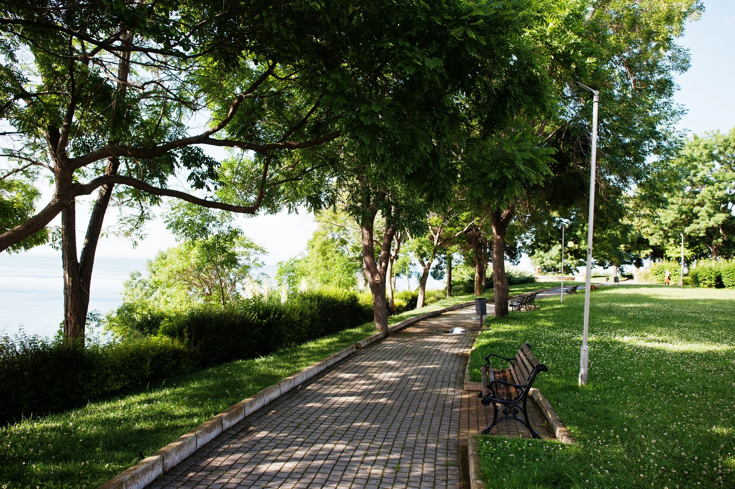
A street tree in a typical urban planting pit has a life expectancy measured in single-digit years. The same species in a park or a suburban yard lives for decades. The difference is not species selection, maintenance, or pollution. It is that the urban tree does not have enough soil, and what soil it has is compacted to a density its roots cannot penetrate.
This is the central engineering problem in urban landscape. Everywhere a tree sits beneath or beside pavement, two requirements are in direct conflict: the pavement needs a compacted subgrade to avoid settlement, and the tree needs an uncompacted one to grow roots. Resolving that conflict is what structural soil and soil cell systems exist to do.
This post covers how much soil a tree actually needs and why, the compaction conflict and the two engineering approaches to it, how drainage below a park works, and the subsurface coordination that determines whether any of it survives.
1. Soil Volume Determines Mature Tree Size
There is a reasonably direct relationship between the volume of usable soil available to a tree and the canopy size it can support. Roots supply water, and the soil is the reservoir the tree draws from between rainfall or irrigation events. A larger canopy transpires more water and needs a larger reservoir.
The working guidance used in urban forestry is on the order of 2 cubic feet of soil per square foot of eventual canopy projection, with variation for climate and soil water-holding capacity. A tree with a 20 foot canopy diameter projects about 314 square feet, so it needs roughly 600 cubic feet of soil. A tree intended to reach a 30 foot canopy needs on the order of 1,000 to 1,500 cubic feet.
1,000 cubic feet
Approximate usable soil volume a large-canopy street tree requires to reach mature size. A conventional 5 by 5 foot tree pit at 3 feet deep provides 75. The gap between those two numbers is why urban street trees rarely reach the size the design drawing showed.
Set against that, a conventional tree pit of 5 by 5 feet at 3 feet deep provides 75 cubic feet. Even a generous 8 by 8 pit at 3 feet provides under 200. The tree is planted into a container roughly a tenth the size it needs, surrounded by compacted subgrade its roots cannot enter, and the outcome follows from that.
Roots respond by doing what they can: growing along the interface between the pit and the pavement base, following utility trenches where the backfill is looser, and surfacing where the pavement lifts. Root damage to pavement is usually read as the tree being a problem. It is more accurately read as the tree having nowhere else to go.
2. The Compaction Conflict
Pavement subgrade is specified to a compaction standard, commonly 90 to 95 percent of maximum dry density, because a subgrade that settles takes the pavement with it. Root growth requires soil below roughly 85 percent of maximum dry density in most textures; above that the pore spaces are too small and too poorly connected for roots to extend and for water and air to move.
Those two requirements are not compatible in the same material, which is why the two available engineering solutions both work by separating the load-bearing function from the root-growing function.
Structural soil
Structural soil is a designed mixture of angular crushed stone and a smaller volume of soil, proportioned so that the stone particles interlock and carry the load through stone-to-stone contact while the soil occupies the voids between them without being compressed.
The stone skeleton can be compacted to pavement subgrade requirements because the load path is through the stone. The soil in the voids remains uncompacted and available for roots. A hydrogel or similar tackifier is typically included to prevent the soil from migrating down through the stone matrix during placement and under vibration.
The limitation is proportion. Because the stone has to remain in continuous contact to carry load, the soil fraction is limited to roughly 20 to 25 percent of the total volume. So a cubic foot of structural soil provides about a quarter of a cubic foot of usable rooting medium, which means achieving 1,000 cubic feet of soil requires something like 4,000 cubic feet of structural soil. That is a large excavation, and the cost reflects it.
Structural soil suits situations where a continuous rooting zone under pavement is wanted, where the excavation depth is available, and where the cost of the volume is acceptable. It is a well-established system with a long performance record.
Suspended pavement and soil cells
The alternative approach is to carry the pavement on a structural frame and fill the space beneath it with uncompacted soil. The frame takes the load; the soil takes none.
Proprietary soil cell systems are modular plastic frames assembled into a matrix below the pavement, backfilled with soil placed at low density, and capped with a deck that supports the pavement base. Because the soil carries no load, it can be a good quality planting soil at a density roots can use, and essentially the entire volume within the cells is usable.
The efficiency is the advantage. Where structural soil delivers about a quarter of its volume as usable soil, a cell system delivers most of it, so achieving the same rooting volume takes roughly a quarter of the excavation. Against that, the cells themselves are a material cost, and the system requires more careful installation because the deck has to be continuously supported and the backfill has to be placed without compacting it.
Both systems require the same thing at the boundary: continuity. A rooting zone that stops at the edge of the tree pit and gives way to compacted subgrade has not solved the problem, it has enlarged the container. The design intent is a continuous rooting corridor connecting multiple trees along a street or through a park, which also allows the trees to share soil volume rather than each requiring its own.
3. Drainage Below the Surface
A park's drainage has to serve two purposes that are usually treated separately: removing surface water so the space is usable, and providing the subsurface drainage that keeps root zones aerobic.
Surface drainage
Lawn and open areas are graded to shed water toward collection points, with slopes generally between 1.5 and 5 percent. Below 1.5 percent, construction tolerance and subsequent settlement can produce flat or reverse-graded areas that pond. Above about 5 percent, mowing and use become difficult and erosion risk rises.
Paved areas within a park drain to inlets, and the inlet capacity and spacing follow from the contributing area and the design storm. On sites subject to post-construction stormwater requirements, some or all of that runoff will need to be managed on site, which brings bioretention and infiltration features into the park design as functional elements rather than as decorative ones.
Subsurface drainage
Saturated soil has no available oxygen, and roots in anaerobic conditions die. Where a park sits on poorly draining subsoil, or where the construction has created a compacted layer that perches water, subsurface drainage is necessary to keep the root zone aerobic.
Perforated pipe underdrains in a granular envelope, laid below the root zone and graded to an outfall, are the standard approach. The outfall is the element most often compromised: an underdrain discharging to a location that itself floods, or to an outlet that silts up and is never cleaned, stops working and the failure appears as unexplained plant decline years later.
On heavily used areas such as sports fields, the drainage requirement is more demanding because the surface has to be playable soon after rainfall, which drives sand-based rootzone construction with a designed perched water table, a distinct engineering approach with its own literature.
The interaction with rooting volume
Soil cell systems and structural soil both sit below pavement and both fill with water if drainage is not provided. A soil cell matrix without an outlet becomes a tank, and the tree it was built for drowns. The drainage design for the rooting zone is part of the system design rather than a separate consideration, and it needs an outfall that will remain functional.
Why Park Soil Fails Before Anything Is Planted
The most common cause of poor plant performance in a new park is compaction during construction, and it happens after the soil specification has been met. Tracked equipment moving across placed topsoil, material stockpiled on finished grade, and traffic during wet conditions all compact the profile to densities that prevent root growth. The remedy is procedural: restrict equipment to designated routes, place soil in lifts from the outside working backward so equipment does not travel over placed material, avoid work in wet conditions, and decompact before planting. Specifying good soil and then driving on it produces a site that performs like poor soil.
4. Subsurface Coordination
A park in an urban setting sits above and among utilities, and the coordination between the landscape and what is underground determines a great deal about what is possible.
Existing utilities. Water, sewer, gas, electric, and telecommunications frequently cross park sites, and each carries clearance requirements and access needs. A tree planted over a sewer line will eventually be removed when the line is repaired, and roots in a joint will eventually cause that repair. Establishing utility locations through record research and field designation before layout is settled avoids planting into a future conflict.
Clearance from tree pits. Utility owners generally require horizontal separation between their facilities and tree planting, typically in the range of 5 to 10 feet depending on the utility and the jurisdiction. Where that separation cannot be achieved, root barriers deflect roots away from the utility, though a barrier reduces the rooting volume available and needs to be accounted for in the volume calculation.
New services within the park. Irrigation, lighting, drinking fountains, restrooms, and power for events all require distribution through the site. Routing these within the rooting zone means future maintenance excavation will cut roots, so the design intent is to run them in defined corridors outside the rooting volume where possible, and to sleeve crossings so that a future repair does not require open excavation.
Soil cells and utility crossings. Where a utility must cross a soil cell zone, the cell system has to accommodate it, either by routing the utility through a sleeved corridor within the cells or by interrupting the cell matrix with a properly supported crossing. Interrupting it without support means the pavement above loses its bearing.
5. Surfaces and Their Subgrade
Park paving carries different loads and serves different purposes than street paving, and the design follows from use.
Pedestrian paths carry light loads but must support maintenance vehicles and, on many sites, emergency vehicle access. A path designed for pedestrians alone and then driven on by a truck fails, so the design vehicle needs to be established rather than assumed.
Permeable paving in a park is attractive both for stormwater management and because it admits water and air to the subgrade below, which benefits adjacent trees. The requirements are the same as for permeable paving anywhere: adequate subgrade infiltration or an underdrain, a storage aggregate base sized for the design storm, and a maintenance regime that prevents clogging. Its use over a rooting zone has the additional benefit that the subgrade is not compacted to conventional standards, though the base course still needs to support the surface.
Unbound surfaces such as decomposed granite and engineered wood fibre are common in parks and have specific requirements. They need containment at edges to prevent migration, adequate depth and compaction of the surfacing itself to remain stable and accessible, and a drainage design that prevents saturation. Where they serve as accessible routes, the surface has to be firm and stable, which not all unbound materials achieve in all conditions.
Conclusion
The defining engineering problem in urban landscape is that trees need uncompacted soil in volumes an urban section does not naturally provide, and the pavement above needs compaction that excludes roots. Structural soil resolves it by carrying load through a stone skeleton with soil in the voids, at the cost of needing roughly four times the excavation volume for a given rooting volume. Soil cells resolve it by carrying the pavement on a frame so the soil beneath carries nothing, at the cost of the cell material and more demanding installation.
Either way, the volume target follows from the intended canopy size, the rooting zone has to be continuous rather than a larger pit, and it has to drain. And the most common failure has nothing to do with any of that: it is compaction of the profile by construction equipment after the soil specification has been satisfied, which produces a site that performs like poor soil no matter what was specified.
