
Long-Span Roof Engineering: Why Self-Weight, Ponding, and Load Path Redundancy Govern the Design
Double the span of a simply supported beam under uniform load and the bending moment goes up by a factor of four. Hold the stress the same and the required section modulus goes up by four as well, which means a deeper, heavier member. That heavier member is itself part of the load, so the demand goes up again, requiring more material still.
At short spans this feedback barely registers. At long spans it dominates. By the time you are spanning 200 or 300 feet, the roof structure is largely carrying itself, and the imposed loads it exists to support are a modest fraction of the total. Every pound of structural efficiency compounds.
That is the first thing that separates long-span roof engineering from ordinary framing. The second is that these structures cover large occupied volumes with relatively few members, so the consequences of any single element failing are disproportionate. This post covers how span drives system selection, why ponding is the characteristic failure mode of flexible roofs, how snow accumulates unevenly on large roofs, and why load path redundancy matters more here than almost anywhere else in building structures.
1. Span Drives System Selection
The efficiency of a spanning system depends on how much of its material is working at useful stress. A solid beam in bending has material near the neutral axis carrying almost nothing, which is wasteful at long spans. Every long-span system is, in one way or another, an attempt to eliminate that dead material.
Steel joists and joist girders (40 to 120 feet). The open web replaces the solid beam web with a triangulated pattern of members carrying axial force, removing material where bending stress is low. Efficient, standardised, and economical across the range that covers most warehouses and distribution centres. Depth typically runs around span over 20 to span over 24.
Trusses (80 to 300 feet). Same principle at larger scale with member sizes engineered specifically rather than selected from load tables. Depth in the range of span over 10 to span over 15 gives efficient chord forces. Fabrication and connection detailing become significant cost components, and transport limits on member length drive the splice locations.
Space frames (100 to 400 feet). A three-dimensional truss spanning in two directions. Highly redundant because load can redistribute through multiple paths, and efficient for square or nearly square plans. The trade-off is a very large number of nodes, each a connection requiring fabrication precision, which makes cost sensitive to node design.
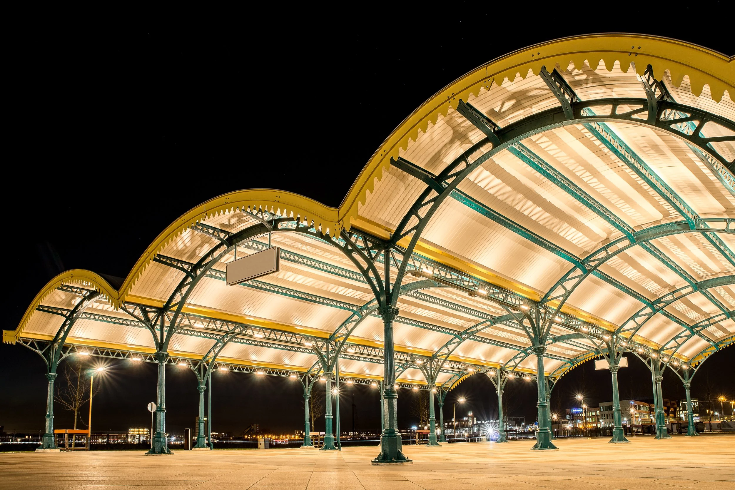
Arches and shells (150 to 600 feet). Curved geometry resolves load primarily into axial compression rather than bending, which uses material far more efficiently. The consequences are large horizontal thrusts at the supports, which must be resisted by buttresses, buried ties, or a tension ring, and sensitivity to buckling and to load patterns that depart from the funicular shape the geometry was derived for.
Cable and tensile systems (200 to 800 feet and beyond). Cables carry pure tension and use steel at its most efficient. The catch is that a cable has no bending stiffness, so shape depends entirely on the load applied, and the structure must be prestressed against a compression ring or mast system to have any stiffness at all under changing load. This is the lightest family of long-span systems and the most demanding analytically, requiring geometric non-linear analysis because the geometry changes significantly under load.
Span²
Bending moment under uniform load scales with the square of span. Because the structure's own weight is part of that load, self-weight becomes the dominant design consideration as spans grow, and structural efficiency compounds.
2. Ponding: The Instability That Feeds Itself
Long-span roofs are flexible. Under load they deflect, and on a low-slope roof, deflection creates a depression. Water flows into that depression. The added water weight increases deflection, which deepens the depression, which admits more water.
If the roof is stiff enough, this converges: each increment of water produces a smaller increment of deflection, and the process reaches equilibrium at a finite ponded depth. If the roof is not stiff enough, it diverges, and the roof continues to accumulate water until it fails. This is ponding instability, and it is a genuine instability in the mathematical sense rather than simply a heavy load.
The parameter that determines which behaviour occurs is roof stiffness relative to the plan area contributing water, and ASCE 7 gives the criterion. Meeting the stiffness requirement is not optional, and it frequently governs member sizing on flat long-span roofs independent of strength.
Why drainage design and structure are the same problem
The ponding check assumes water can leave the roof through the drainage system. Where a primary drain blocks, the water level rises to the secondary drainage, and the design has to remain stable at that higher level. This makes secondary drainage, whether scuppers or overflow drains, a structural safety item rather than a plumbing convenience.
Scupper and overflow drain elevation directly sets the maximum static water depth the roof can experience. Setting them too high, or omitting them, removes the bound on how much water can accumulate. A significant fraction of documented low-slope roof collapses involve blocked primary drains combined with inadequate or absent secondary drainage, on roofs that were otherwise adequately designed.
Camber is the other tool. Fabricating trusses and joists with an upward curvature that offsets dead load deflection means the roof is close to its intended profile in service rather than already dished before any water arrives. Camber has to be specified and it has to survive erection; a truss cambered in the shop and then forced flat during erection to match an adjacent element has lost the benefit.
3. Snow Does Not Land Evenly on a Large Roof
Balanced snow load is a design convenience, not a description of what happens. On any roof with geometry that interrupts wind flow, snow redistributes, and on large roofs the redistribution can produce local loads several times the balanced value.
Drift at height changes. Wherever a lower roof adjoins a higher one, or a parapet, screen wall, or mechanical enclosure interrupts flow, snow deposits in the lee. Drift surcharge decreases with distance from the obstruction, producing a triangular load distribution. On long-span roofs with rooftop equipment, this produces concentrated load in locations that may be near midspan of a truss.
Valley accumulation. Multi-span roofs with a valley between adjacent structures collect snow that slides and blows into the low point. The design load in the valley can substantially exceed the balanced load, and the geometry that creates the valley is often driven by architectural or drainage considerations without the snow consequence being evaluated.
Unbalanced load on curved and gable roofs. Wind removes snow from the windward slope and deposits it on the leeward, producing an asymmetric load case. For an arch, this is more significant than the magnitude alone suggests, because an arch is efficient under loading matching its funicular shape and much less so under asymmetric loading, which introduces bending the section may not be proportioned for.
Sliding snow. Snow shedding from a higher roof onto a lower one delivers a concentrated load and, on impact, a dynamic component. Where a long-span roof sits below a taller structure, this needs explicit consideration.
Rain-on-Snow and the Drainage Interaction
A snow-covered roof with blocked drains that then receives rainfall combines several of these mechanisms at once. The snow holds water that would otherwise run off, the added weight deflects the roof, the deflection ponds more water, and the drainage that would relieve it is obstructed by ice at the drain. Cold-climate roof failures frequently trace to this combination rather than to any single load being exceeded. Heat-traced drains, adequate insulation to prevent melt-refreeze at eaves, and secondary drainage sized and located to function when primary drains ice over are the design responses.
4. Redundancy and Progressive Collapse
A distribution centre roof might use fifty joists spanning between girders. If one joist fails, load redistributes to the deck and to adjacent joists, and the failure is likely to remain local. A stadium roof might use eight primary trusses. If one fails, there is nowhere for its load to go.
This is the structural argument for redundancy in long-span systems, and it is why the number of primary load-carrying elements matters as much as the capacity of each. Highly determinate systems with few members are efficient and vulnerable. Redundant systems carry alternate load paths that allow the structure to survive the loss of a single element while damaged.
Where redundancy is typically weakest
Connections are the usual answer. A truss chord splice, a bearing detail, a cable anchorage, or a space frame node concentrates the force from a large tributary area into a small assembly. Failure of one connection can release a member entirely, whereas a member with a local defect often retains partial capacity.
Compression members are the second area. A tension member with 20 percent section loss retains most of its capacity. A compression member that buckles loses capacity abruptly and completely, and buckling capacity depends on bracing that may itself be provided by other members which are also loaded. Loss of a brace can trigger buckling of the member it braced, which can unload into adjacent members and propagate.
The design responses are to detail connections to be stronger than the members they join, so that yielding occurs in the member where it is ductile and detectable, to provide bracing systems with their own redundancy, and where the consequence of collapse is high, to explicitly check alternate load paths under notional removal of individual key elements.
5. Erection Is a Load Case
Long-span structures are frequently at their most vulnerable before they are complete, because the load paths the design relies on are not yet in place.
An arch is not an arch until it closes; before that it is a pair of cantilevers requiring temporary support. A cable roof has no stiffness until it is prestressed, and the sequence of stressing determines the geometry that results. A space frame assembled at ground level and lifted experiences a completely different load distribution during the lift than in service. A truss is laterally unstable until its bracing is installed, and its compression chord can buckle under self-weight alone if unbraced over its full length.
The engineering consequence is that erection sequence, temporary works, and stability during construction are part of the structural design rather than a contractor concern to be resolved later. Several notable long-span failures have occurred during erection rather than in service, and in most cases the completed structure would have been entirely adequate.
Conclusion
Long-span roof engineering is governed by a handful of things that matter far less at ordinary spans. Self-weight dominates because moment scales with the square of span, so system selection is fundamentally about eliminating material that is not working. Ponding is a genuine instability rather than a load case, which makes stiffness a strength-independent design requirement and makes secondary drainage a structural safety item. Snow redistributes into drifts and valleys that can multiply the design load locally, particularly around the rooftop equipment these buildings inevitably carry.
And because these structures span large occupied spaces with few members, redundancy and connection detailing carry consequences they would not carry in a repetitive framing system. The same reasoning applies during erection, when the load paths the design assumes are only partly in place.
