
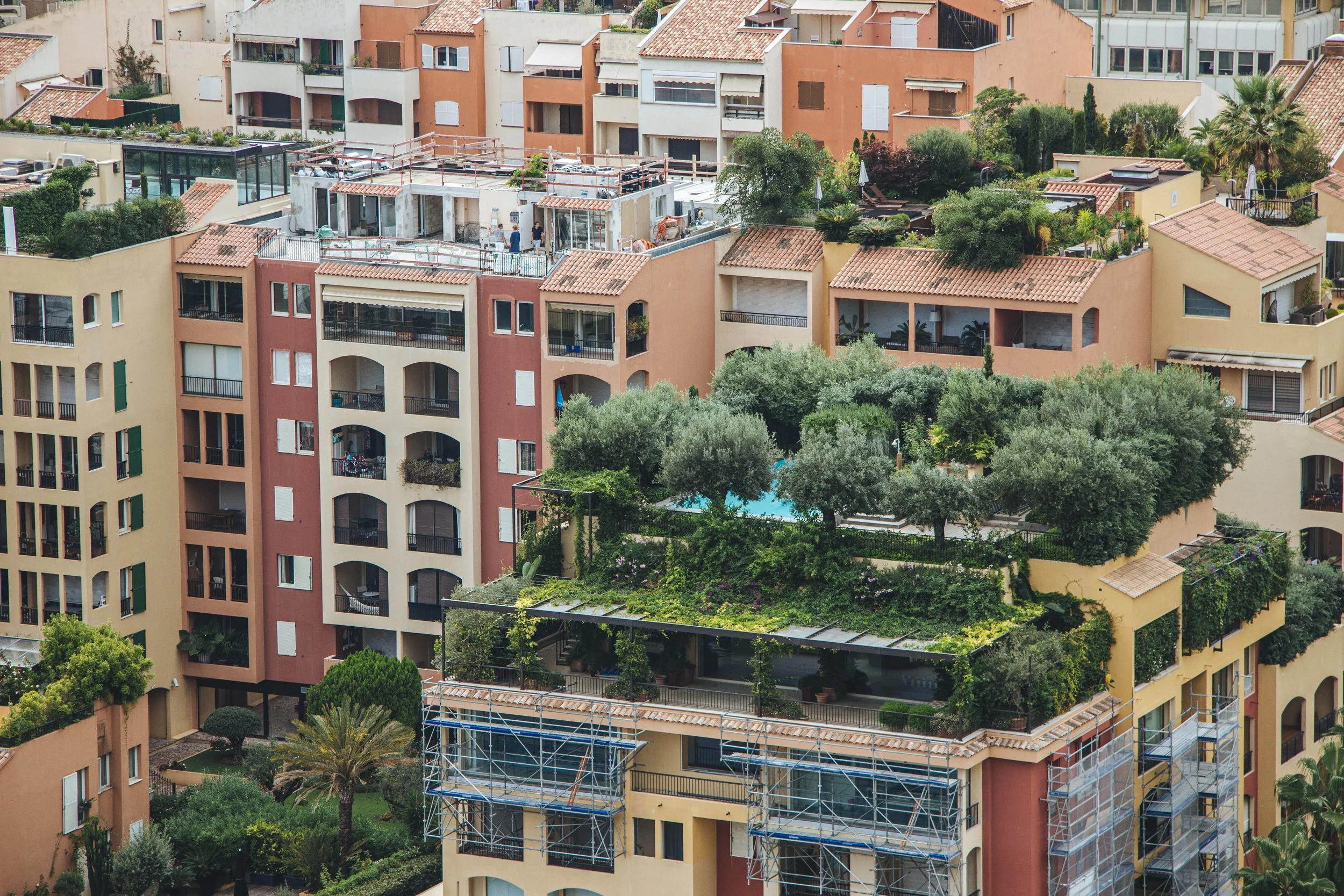
A green roof puts a saturated growing medium, a drainage layer, and a permanent planting on top of a waterproofing membrane that is now buried and inaccessible. That single fact organises everything about how these assemblies are designed.
The membrane has to last as long as the roof, because reaching it means removing everything above it. Leaks have to be locatable without excavating the whole roof to find them. The assembly has to stay in place under wind on a surface where loose material is available to be lifted. And the structure has to carry the medium at full saturation, not at the weight it is delivered in.
This post covers how the assembly layers work, what saturated loading actually means for the structure, why leak detection design matters more here than on a conventional roof, how wind uplift is resisted on a system with no mechanical attachment, and what determines long-term performance.
1. Extensive, Intensive, and What Separates Them
Green roof assemblies are conventionally divided by media depth, and the depth determines almost everything else.
Extensive systems use roughly 3 to 6 inches of media, support drought-tolerant low-growing vegetation, principally sedums and some hardy grasses and forbs, and impose a saturated load in the range of 15 to 35 psf. They generally require no irrigation once established beyond drought contingency, and maintenance is limited to weeding and periodic inspection. Most retrofits onto existing roofs are extensive systems, because the load is within what many roofs can accept.
Intensive systems use 8 inches to several feet of media, support shrubs, perennials, and trees, and impose saturated loads from 80 psf up to 200 psf or more with deeper profiles. They require irrigation, drainage design comparable to a ground-level landscape, and regular horticultural maintenance. They are effectively a designed landscape and require the structure to be designed for them from the outset.
Semi-intensive systems sit between, at roughly 6 to 12 inches, supporting a broader plant palette than sedum alone while keeping the load manageable. This range covers a large share of new construction green roofs because it delivers meaningfully better ecological and aesthetic performance than an extensive system without the structural implications of a full intensive one.
The distinction matters beyond the load because deeper media holds more water, which means better stormwater retention and better plant survival through drought, but also longer sustained saturated periods after rainfall and higher drainage demand.
2. Saturated Load Is the Design Case
Green roof media is engineered mineral aggregate with a modest organic fraction, and its dry and saturated weights differ substantially. Typical extensive media weighs around 40 to 60 pounds per cubic foot dry and 65 to 95 pounds per cubic foot at maximum water capacity.
The design load uses the saturated value, because that is the condition after any significant rainfall, and it applies to the full media depth plus the water retained in the drainage layer and the weight of the mature vegetation.
Maximum water capacity
The saturated condition is the design case, not the delivered weight. Green roof media at maximum water capacity typically weighs 65 to 95 lb/ft³ against 40 to 60 dry, and the difference across a full roof is the load that has caught out more than one retrofit.
What else contributes
Snow load applies on top of the green roof load, and there is a subtlety: the green roof does not reduce snow load, and in some conditions the vegetation and the surface texture increase retention of drifting snow relative to a smooth membrane roof.
Live load for maintenance access has to be considered where people will walk on the roof, and where the roof is designed for occupancy the assembly load is added to the occupancy live load rather than substituting for it.
Point loads from any elements within the green roof, planters, seating, paving areas, equipment, trees with root balls, are separate from the distributed media load and have to be assessed against the framing beneath them. A tree on an intensive roof is a substantial concentrated load in both weight and, once mature, in wind-induced overturning transmitted into the roof structure.
On a retrofit
Adding a green roof to an existing building requires the same structural assessment as any added roof load: establishing the framing and its capacity, the current actual dead load including accumulated roofing layers, and the current code snow or live load. The available reserve capacity is what determines the assembly depth that is feasible.
Where the reserve is limited, the options are a shallower extensive system, a lightweight media formulation, or partial coverage concentrated over the strongest parts of the structure. What does not work is designing the assembly first and checking the structure afterward.
3. The Assembly Layers
From the structural deck upward, a green roof assembly is a defined sequence, and each layer has a specific job.
Waterproofing membrane. The primary barrier. Because it becomes inaccessible, the requirement is a system with a design life matching or exceeding the intended life of the green roof, and one that can be tested for integrity before it is covered. Fully adhered systems are generally preferred over loose-laid because a leak in an adhered membrane stays local, whereas water beneath a loose-laid membrane can travel and emerge far from its entry point.
Root barrier. Prevents roots from penetrating the waterproofing. Some membranes are inherently root resistant and require no separate barrier; others need a dedicated layer. Root resistance is established by standardised testing over a multi-year exposure, and specifying a membrane as root resistant without that test evidence is a risk, particularly under an intensive system with woody plants.
Protection layer. Shields the membrane from physical damage during construction and from the drainage layer above. Construction damage is a major source of green roof leaks, because the membrane is installed early and then walked on, loaded with material, and worked over by other trades before it is covered.
Drainage layer. Removes water in excess of what the media retains and conveys it to the roof drains. Typically a moulded polymer sheet with cups or dimples, or a granular layer. Cupped products retain some water for plant use in the cups while draining the excess, which improves drought performance.
Filter fabric. Separates the media from the drainage layer, preventing fines from washing down and clogging it. Its permeability has to exceed the media's infiltration rate, and its aperture has to be fine enough to retain the media fines. A filter that clogs causes the media to saturate and the plants to fail, and it is not accessible for replacement.
Growing media. Engineered rather than soil. Predominantly lightweight mineral aggregate, expanded shale, expanded clay, or pumice, with a limited organic fraction, typically 10 to 20 percent by volume. Higher organic content is tempting because it improves initial fertility, but organic matter decomposes and the media shrinks as it does, which reduces depth over time and can lead to a media layer that no longer covers the plants' root zone.
Vegetation. Selected for the media depth, the climate, and the exposure. Rooftop conditions are harsher than ground level: more wind, more solar exposure, more temperature extremes at the media surface, and limited rooting depth. Plants that thrive at grade in the same climate frequently fail on a roof.
4. Leak Detection Design
A leak in a conventional roof is located by inspection from above. A leak beneath a green roof is not, and the difference in consequence is large enough that leak detection should be designed rather than left to be dealt with when a leak appears.
Electronic leak detection
Electrical integrity testing works by establishing an electrical potential across the membrane, with the deck or a conductive layer below acting as one electrode and water on the surface as the other. Where the membrane is intact it insulates; where there is a breach, current flows and the location can be traced.
Two approaches exist. A test conducted before the assembly is installed verifies integrity at the point where a defect can be repaired easily, and this should be a specified hold point on every green roof. A permanently installed monitoring grid, with conductive elements beneath the membrane wired to a monitoring panel, allows the roof to be tested at any point in its life without disturbing the assembly. The permanent system costs more at installation and is worth it on assemblies where investigating a leak by excavation would be seriously disruptive.
Compartmentalisation
Dividing the roof into drainage compartments with water-tight separations means a leak is confined to one compartment, which reduces the area that has to be investigated and the area that has to be stripped for repair. The compartments align with drainage zones so that each has its own outlet.
Without compartmentalisation, water entering at one point on a large roof can travel beneath the membrane and emerge anywhere, and locating the actual breach becomes a matter of removing assembly until it is found.
Test Before Covering, Always
Flood testing or electronic integrity testing of the completed waterproofing, before any protection or drainage layer is installed, is the single highest-value quality control step on a green roof project. At that stage a defect is a patch. After the assembly is installed it is an excavation. This should be a specified hold point with sign-off required before the following trades proceed, and compressing it under schedule pressure is a false economy that has produced a great many expensive green roof leak investigations.
5. Wind Uplift
A green roof presents a surface of loose granular media and vegetation to the wind, and both can be lifted. The design has to prevent both erosion of the media and displacement of the assembly.
Media erosion
Before vegetation establishes, the media surface is exposed and can be scoured by wind, particularly at roof edges and corners where velocities are highest. The responses are surface protection during establishment, wind erosion blankets or netting held down at the perimeter, media formulations with adequate particle size so the fraction available to be lifted is small, and vegetated mats or pre-grown blankets rather than plugs or seed in high-exposure locations.
Once vegetation covers the surface, the media is substantially protected, which makes rapid establishment a wind design objective as well as a horticultural one.
Assembly uplift
The assembly as a whole is generally held down by its own weight, since it is not mechanically fastened. Whether that weight is sufficient depends on the uplift pressure, which varies across the roof by zone, with corners experiencing the highest suction, then perimeters, then the field.
Where the assembly weight is insufficient in the high-suction zones, the responses are a heavier ballast at the perimeter and corners, typically a band of larger aggregate or paver, mechanical restraint of edge components, or a wind-secured system with the layers interconnected and anchored.
Edge details are where uplift concentrates. A perimeter where the assembly terminates against a parapet or an edge condition needs to be detailed so that wind cannot get beneath the layers and lift them, which means the edge components have to be secured rather than simply abutted.
6. Long-Term Performance
Green roofs are frequently presented as low maintenance, which is true relative to a conventional landscape and untrue in absolute terms. Several things change over the assembly's life.
Media depth reduces. The organic fraction decomposes, and the media settles under its own weight and under wetting cycles. A system installed at 4 inches may be at 3 after a decade, which reduces water holding capacity and stresses plants. Periodic media top-up is a maintenance activity that should be anticipated.
Plant communities shift. The installed planting is not what will be there in ten years. Some species dominate, others disappear, and volunteers arrive by wind and bird. This is not necessarily failure, and a shifting community can be more resilient than the installed one, but it means the roof will not look like the design drawing indefinitely.
Drainage components can clog. Drains, filter fabric, and the drainage layer accumulate fines and organic debris. Drain inspection chambers, which allow access to the roof drain without disturbing the assembly, are what make this maintainable and are frequently omitted.
Irrigation systems fail unnoticed. On systems with irrigation, a failed zone or a blocked emitter produces plant loss in a pattern that is easy to attribute to plant selection rather than to the system. Periodic verification of the irrigation is worth more than it costs.
Access for all of this has to be designed in. A green roof with no safe access route, no fall protection, and no way to get materials up is a green roof that will not be maintained, and the maintenance regime the design assumed will not happen.
Conclusion
A green roof buries a waterproofing membrane under an assembly that is expensive to remove, and that single fact drives the design. The membrane specification, the integrity test before covering, the leak detection provision, and the drainage compartmentalisation all follow from the cost of reaching a defect later.
The structural design case is the media at maximum water capacity with snow and live load on top of it, not the delivered weight. Wind uplift is resisted by assembly weight, which means the high-suction zones at corners and perimeters need heavier treatment, and the media surface needs protection until vegetation establishes.
And the assembly changes over time. Media depth reduces as organic matter decomposes, plant communities shift, drainage components accumulate debris. Designing the access that makes maintenance possible is what determines whether any of it gets attended to.
