
CO2 Pipelines and Injection Wells: The Engineering of Putting Carbon Underground Permanently
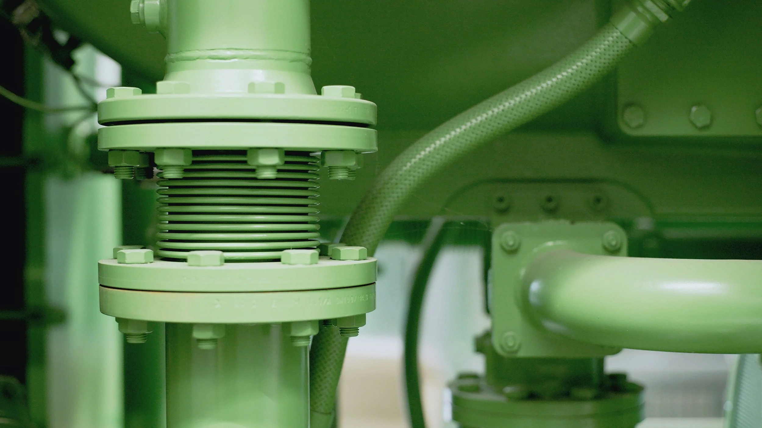
Carbon dioxide is a strange substance to move through a pipeline. At the pressures and temperatures used for pipeline transport, it isn't a gas and it isn't quite a liquid. It's supercritical: a phase where it has roughly the density of a liquid and the viscosity of a gas, flowing through pipe more like a dense fluid than like the compressible gas most pipeline engineers are used to designing for.
That single physical property drives most of what makes CO2 pipeline and injection engineering different from natural gas engineering. Supercritical CO2 requires higher operating pressures. It behaves differently during a depressurization event. It reacts with water to form an acid that attacks carbon steel. And when it's injected into a deep geologic formation, its density relative to the formation brine determines whether it rises, spreads, or stays put over the decades that the storage has to remain secure.
This post covers the engineering of CO2 transport and geologic storage: why supercritical phase behavior governs pipeline design, what makes a formation suitable for permanent storage, how injection wells are engineered and monitored, and where the technical failure modes actually are.
1. Why Supercritical Phase Behavior Governs the Design
Carbon dioxide has a critical point at 88 degrees Fahrenheit and 1,071 psi. Above both of those thresholds, the distinction between liquid and gas disappears. The substance becomes a single supercritical phase with properties that fall between the two.
For pipeline transport, this is desirable. In the supercritical state, CO2 has a density of roughly 600 to 800 kilograms per cubic meter, which is comparable to a light hydrocarbon liquid. That density means a given pipe diameter can carry far more mass of CO2 per hour than it could if the CO2 were transported as a gas at low pressure. The economics of moving millions of metric tons per year effectively require supercritical transport.
The engineering consequence is that CO2 pipelines have to be maintained above the critical pressure along their entire length, typically at operating pressures between 1,200 and 2,200 psi. That's substantially higher than most natural gas transmission lines, which commonly operate between 600 and 1,000 psi. Higher operating pressure means thicker pipe wall for a given diameter and grade, which drives material cost and affects welding procedures, hydrostatic testing requirements, and the design of pressure control and relief systems.
The phase transition problem
The most technically consequential aspect of supercritical CO2 behavior is what happens when the pressure drops. If pressure falls below the critical point anywhere along the pipeline, the CO2 transitions from a single supercritical phase to a two-phase mixture of gas and liquid. Two-phase flow in a pipeline designed for single-phase flow creates slugging, pressure fluctuation, and mechanical stress on the pipe and equipment that neither was designed to handle.
This means CO2 pipeline hydraulic design has to maintain adequate pressure at every point along the route, accounting for elevation changes, friction losses, and temperature variation. Booster compressor stations are placed along longer routes to maintain the pressure profile. Elevation profiles matter more than they do in gas pipeline design because the density of supercritical CO2 means the static head from an elevation gain is significant: climbing 1,000 feet of elevation costs roughly 300 psi of pressure, which for a pipeline operating near its minimum threshold can be the difference between single-phase and two-phase flow.
1,071 psi / 88°F
The critical point of carbon dioxide. Above both thresholds, CO2 becomes supercritical: liquid-like density, gas-like viscosity. Pipeline design has to maintain conditions above this point along the entire route.
2. Corrosion: The Water Problem
Dry supercritical CO2 is essentially non-corrosive to carbon steel. Wet CO2 is aggressively corrosive. The mechanism is straightforward: CO2 dissolved in water forms carbonic acid, which attacks the steel through a well-understood electrochemical process. Corrosion rates in wet CO2 service can exceed 10 millimeters per year at elevated temperature and pressure, which would destroy a pipeline in a matter of months rather than decades.
The engineering response is dehydration. CO2 streams from capture facilities carry water vapor picked up during the capture process, and that water has to be removed before the stream enters the pipeline. Typical pipeline specifications limit water content to somewhere between 20 and 500 parts per million by volume, well below the saturation point at operating conditions, so that no free water phase can form anywhere along the route including at the coldest point in the pipeline's thermal profile.
Meeting that dehydration specification requires a glycol dehydration unit or a molecular sieve system at the capture facility, and it requires continuous monitoring of the water content in the stream entering the pipeline. A dehydration system upset that allows a wet slug to enter the pipeline can initiate corrosion at low points along the route where the water accumulates, and that corrosion continues after the upset is corrected.
The other stream composition variables that matter are the impurities that come along with the captured CO2. Oxygen accelerates corrosion in the presence of water. Hydrogen sulfide introduces sulfide stress cracking risk in high-strength steels. Nitrogen and argon affect the phase behavior, shifting the critical point and requiring the pipeline hydraulic design to account for the actual stream composition rather than pure CO2 properties. Pipeline specifications typically set limits on each of these, and the capture facility design has to meet them.
3. Depressurization Behavior and Route Siting
When a natural gas pipeline ruptures, the gas escapes, disperses upward because it's lighter than air, and either ignites or dissipates. When a supercritical CO2 pipeline ruptures, the behavior is different in ways that matter for route siting.
The CO2 rapidly expands and cools as it depressurizes, a process that can produce temperatures well below freezing at the rupture point and can generate solid CO2 (dry ice) in the immediate vicinity. The expanded CO2 gas is roughly 1.5 times denser than air, which means it doesn't rise and disperse the way natural gas does. It flows along the ground surface and accumulates in low-lying terrain, depressions, and enclosed spaces.
CO2 is not toxic in the way that hydrogen sulfide is, but it displaces oxygen. At concentrations above roughly 10 percent by volume, it causes rapid unconsciousness. At higher concentrations, it's fatal. The 2020 pipeline rupture in Satartia, Mississippi, where a CO2 line failure sent a dense plume into a low-lying area and hospitalized dozens of people, is the reference case that the industry and regulators have been working from since.
The engineering response has two components. First, route siting has to account for terrain: pipeline routes should avoid running through or immediately adjacent to low-lying populated areas where a release plume would concentrate. Dispersion modeling for a range of rupture scenarios is now standard practice in route selection for CO2 lines near populated areas. Second, the spacing of isolation valves along the route determines how much CO2 can be released from a single rupture. Closer valve spacing in higher-consequence areas limits the release inventory, at the cost of more valve stations to install and maintain.
Design Standards for CO2 Pipelines
CO2 pipelines in the United States are regulated under 49 CFR Part 195, the same regulation that covers hazardous liquid pipelines, rather than the natural gas pipeline regulations in Part 192. PHMSA has been developing updated rules specific to CO2 service, addressing dispersion modeling requirements, valve spacing, emergency response planning, and the technical differences between gaseous and supercritical CO2 transport. Engineers working on CO2 pipeline design should verify current regulatory status, since this is an actively developing area of the code.
4. What Makes a Geologic Formation Suitable for Storage
The end of the CO2 pipeline is an injection well, and the injection well delivers the CO2 into a geologic formation that has to hold it permanently. The characteristics that make a formation suitable are specific and measurable.
Depth greater than roughly 800 meters: This is the depth at which the natural formation pressure and temperature keep injected CO2 in its supercritical state. Above that depth, the CO2 would transition to a gas phase, occupying dramatically more volume and becoming much more buoyant relative to formation fluids. The 800-meter threshold is a practical floor for permanent storage.
Adequate porosity and permeability: Porosity determines how much CO2 the formation can hold per unit volume of rock. Permeability determines how readily the CO2 can move through the formation away from the injection point. Low permeability means injection pressure builds rapidly and the achievable injection rate is limited. Target formations typically need permeability above roughly 10 millidarcies and porosity above 10 percent, though the specific requirements depend on the intended injection rate.
A competent confining layer above the storage formation: The caprock is what prevents the CO2, which is buoyant relative to the formation brine, from migrating upward toward shallower formations and eventually toward drinking water aquifers or the surface. The caprock needs low permeability, sufficient thickness, lateral continuity across the area the CO2 plume will occupy, and adequate mechanical strength to resist fracturing under the pressure increase that injection creates.
Absence of transmissive faults or unplugged wellbores: A fault that cuts through the caprock and is hydraulically transmissive provides a pathway for CO2 to migrate upward. An old, improperly plugged oil or gas well penetrating the storage formation does the same thing. In mature oil and gas basins, which often have the best storage geology, legacy wellbore integrity is one of the most significant technical risks in site characterization. Some prospective storage sites have thousands of legacy wells within the area of review.
How the CO2 stays put
The trapping mechanisms that hold injected CO2 in place operate on different timescales, and understanding the sequence explains why storage security increases over time rather than degrading.
Structural and stratigraphic trapping works immediately: the caprock physically prevents upward migration, the same way it trapped hydrocarbons in oil and gas reservoirs for millions of years. Residual trapping occurs over years to decades: as the CO2 plume migrates through the pore network, a fraction of it becomes immobilized as disconnected bubbles held in place by capillary forces. Solubility trapping occurs over decades to centuries: CO2 dissolves into the formation brine, and the CO2-saturated brine is denser than the surrounding brine, so it sinks rather than rising. Mineral trapping occurs over centuries to millennia: dissolved CO2 reacts with formation minerals to precipitate stable carbonate minerals, converting the CO2 into rock.
The engineering implication is that the highest-risk period for a storage site is during and immediately after active injection, when the plume is mobile and the formation pressure is elevated. That's why monitoring requirements are most intensive during injection and the immediate post-injection period, and why post-injection monitoring can be reduced once the plume has demonstrably stabilized.
5. Injection Well Engineering
A CO2 injection well is a purpose-built structure that has to maintain its integrity for the duration of injection and for the long post-closure period after. The design challenges are specific to CO2 service.
Materials and cement
Standard oilfield Portland cement degrades when exposed to carbonic acid over long periods. The carbonation reaction converts calcium hydroxide and calcium silicate hydrate in the cement to calcium carbonate, which initially reduces permeability but with continued exposure leads to leaching and loss of mechanical integrity. CO2-resistant cement formulations, typically incorporating pozzolanic materials, latex additives, or in some designs geopolymer systems, are used in the injection interval and across the caprock to maintain the cement sheath's sealing function.
Tubing and casing materials face the same wet-CO2 corrosion mechanism that pipelines do, with the added complication that formation brine is present in the wellbore environment by definition. Corrosion-resistant alloys, typically 13 chrome or higher stainless grades, are standard for the injection tubing. The casing across the injection interval may be carbon steel with corrosion-resistant cement and a packer isolating the annulus, or CRA depending on the specific design and the operator's risk tolerance.
Injection pressure and formation fracture limits
The single most important operating constraint on a CO2 injection well is that the injection pressure must remain below the fracture pressure of the caprock. Exceeding it creates fractures that provide a migration pathway. Regulatory frameworks typically require injection pressure to be limited to some percentage, commonly 90 percent, of the formation fracture pressure, with continuous downhole pressure monitoring to verify compliance.
Determining the fracture pressure requires a step-rate test or a diagnostic fracture injection test conducted before the well enters service. The result establishes the maximum allowable surface injection pressure for the well, which then constrains the maximum achievable injection rate. Formations with low permeability may reach their pressure limit at injection rates well below what the project economics assumed, which is why formation testing during site characterization is critical to establishing realistic project capacity.
Monitoring the plume
Verifying that the injected CO2 stays where it's supposed to requires a monitoring program that operates across multiple scales. Downhole pressure and temperature gauges in the injection well and in dedicated monitoring wells track the pressure response of the formation. Time-lapse 3D seismic surveys, repeated at intervals during injection, image the CO2 plume directly by detecting the change in seismic velocity where CO2 has displaced brine in the pore space. Above-zone monitoring intervals, completed in a permeable formation above the caprock, provide an early warning if CO2 or displaced brine migrates upward. Groundwater monitoring wells in shallow aquifers verify that drinking water resources are unaffected.
The monitoring program design is site-specific and has to be defensible to the regulating authority. It's also a long-term commitment: post-injection monitoring periods extend for decades, and the financial assurance requirements that operators must satisfy account for the cost of maintaining that monitoring after injection revenue has stopped.
For Engineers Entering This Sector
CO2 storage engineering draws heavily on petroleum reservoir engineering, geotechnical characterization, and pipeline engineering, but the design objectives are different in an important way. In oil and gas production, the goal is to get fluids out of the formation efficiently. In CO2 storage, the goal is to put fluid in and guarantee it stays for a thousand years. That inversion changes what matters: caprock integrity, wellbore sealing, and long-term monitoring are the design drivers, not production rate. Engineers coming from oil and gas backgrounds bring highly relevant skills but need to internalize that the permanence requirement is the governing constraint.
Conclusion
CO2 transport and storage engineering is a distinct technical discipline that sits at the intersection of pipeline engineering, reservoir characterization, and wellbore integrity. The physics that drives it, supercritical phase behavior, carbonic acid corrosion, buoyancy-driven plume migration, and the multi-timescale trapping mechanisms that eventually make storage permanent, is well characterized and understood.
The engineering challenges are real: maintaining single-phase flow across varied terrain, meeting dehydration specifications reliably, siting pipeline routes with dispersion behavior in mind, characterizing formations and caprocks with enough confidence to commit to permanent injection, and designing wells and monitoring programs that will function correctly for decades after the project's active phase ends. None of these are unsolved problems. All of them require careful, site-specific engineering rather than standard designs applied uniformly.
