
Post-Tensioned Parking Structures: Corrosion Mechanics, Failure Modes, and What Assessment Actually Finds
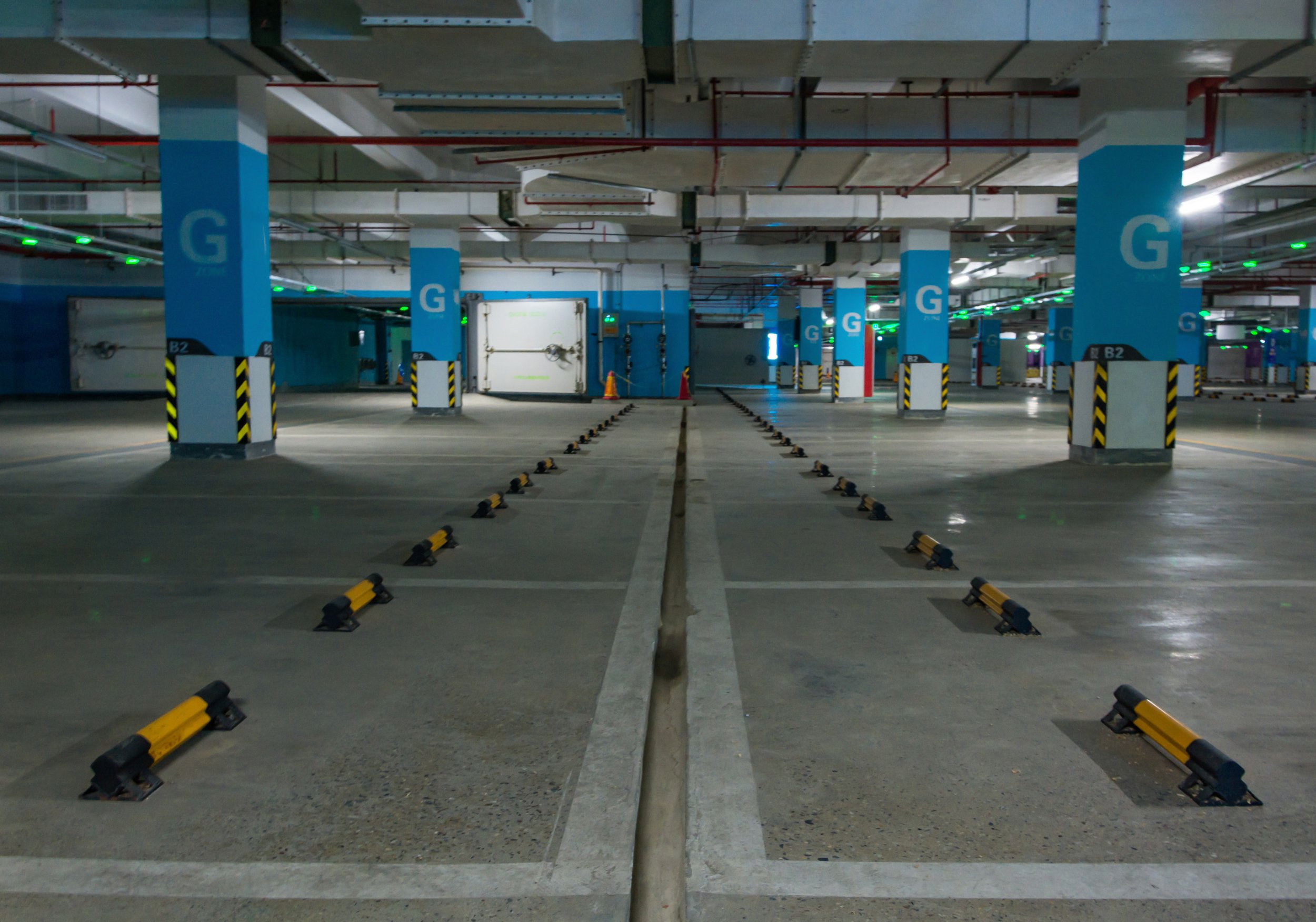
A post-tensioned concrete slab depends on a force that you cannot see, cannot easily measure, and cannot verify by looking at the structure. The tendons running through the slab carry between 25,000 and 200,000 psi of tension, and that tension is the reason the slab can span 60 feet with a thickness that ordinary reinforced concrete would need twice as much depth to achieve.
If a tendon loses that tension, the slab loses the capacity it was designed around. And unlike conventional reinforced concrete, where corrosion of the rebar produces progressive cracking and deflection that give clear visual warning long before capacity is compromised, post-tensioned tendon corrosion can progress to failure with very little surface indication.
This post covers the mechanics of how PT tendons deteriorate, why the failure mode is different from conventional reinforcement, what condition assessment methods can actually detect, and how repair options are selected based on what the assessment finds.
1. What the Prestressing Force Actually Does
Concrete is strong in compression and weak in tension. In a conventionally reinforced slab, the concrete cracks in the tension zone under service load, and reinforcing steel across the crack carries the tensile force. The cracks are expected, the design accounts for them, and crack width limits govern serviceability.
Post-tensioning changes the stress state before service load is applied. Tendons stressed after the concrete cures apply a compressive force to the section that offsets the tensile stress that service loading would otherwise produce. If the prestress is sufficient, the section stays in compression throughout, and no flexural cracking occurs.
The tendon profile matters as much as the force. In a typical slab, tendons are draped: positioned low at midspan where positive moment is greatest, and high over supports where negative moment governs. That profile means the tendon force applies an upward load along the span through the curvature of the tendon, directly counteracting a portion of the gravity load. This balanced-load effect is what allows PT slabs to be thinner than reinforced concrete equivalents.
Both effects depend on the tendon maintaining its tension. Prestress loss from a corroded or fractured tendon removes both the compressive stress and the balancing load, and the section reverts to behaving like an under-reinforced concrete slab with insufficient conventional reinforcement to carry the design load.
2. Bonded and Unbonded Systems Fail Differently
Understanding a PT structure's deterioration risk starts with knowing which system it uses, because the corrosion pathways and the consequences of tendon failure are substantially different.
Unbonded systems
In an unbonded system, each individual strand is coated with corrosion-inhibiting grease and encased in an extruded plastic sheath. The strand is free to move within the sheath along its length, and the prestress force transfers to the concrete only at the anchorages at each end.
Corrosion protection depends on the continuity of the sheath and grease. Where the sheath is damaged, at anchorage terminations, at construction joints, at points where the sheath was nicked during installation, water and chlorides can reach the strand. Because the strand is unbonded, corrosion products and water can migrate along the strand inside the sheath, spreading the corroded zone well beyond the point of initial ingress.
The critical consequence is that in an unbonded system, a strand failure anywhere along its length releases the entire prestress force in that strand across its full length. The strand is only anchored at the ends, so if it fractures at midspan, the force is lost across every span the tendon passes through. A single strand fracture in a multi-span unbonded tendon compromises the prestress in all of those spans simultaneously.
The energy release is also significant. A strand fracturing under load retracts violently, and in documented cases has driven anchorage hardware out through the concrete face.
Bonded systems
In a bonded system, tendons run inside metal or plastic ducts that are filled with cementitious grout after stressing. The grout bonds the tendon to the surrounding concrete along its full length and provides a highly alkaline environment that passivates the steel, the same protection mechanism that protects rebar in sound concrete.
When the grouting is complete and void-free, bonded systems have excellent corrosion durability. The failure mode when it does occur traces to grout voids: incomplete filling of the duct leaves air pockets, typically at high points in the tendon profile where trapped air accumulated during grouting. Those voids provide space for water to collect, and the steel in a void has no grout protection.
The advantage of the bonded system is that a strand fracture is local. Because the tendon is bonded to the surrounding concrete along its length, force transfers back into the tendon within a development length on either side of the break. A fracture doesn't destroy prestress across the entire tendon run the way it does in an unbonded system. This makes bonded systems more damage-tolerant, though it also means a fracture may be harder to detect since the global structural response barely changes.
1.0 to 1.5 lb/yd³
The chloride concentration threshold at the steel that initiates active corrosion by breaking down the passive oxide film. Below this level, the alkaline concrete environment protects the steel indefinitely. Above it, corrosion proceeds.
3. The Corrosion Mechanism
Steel embedded in sound concrete is protected by the concrete's high alkalinity, around pH 12.5 to 13, which maintains a passive oxide film on the steel surface. That film prevents the electrochemical reaction that constitutes corrosion. Steel in that condition does not corrode, essentially indefinitely.
Two mechanisms break down that protection.
Chloride ingress. Chloride ions from de-icing salt or marine exposure penetrate the concrete through the pore network, driven by diffusion when the concrete is saturated and by capillary absorption during wetting and drying cycles. When the chloride concentration at the steel reaches roughly 1.0 to 1.5 pounds per cubic yard, the ions locally break down the passive film and initiate pitting corrosion. Chloride-initiated corrosion is characteristically localized: deep pits rather than uniform section loss, which is significant because a pit can reduce a strand's effective section far more than the total mass of steel lost would suggest.
Carbonation. Atmospheric carbon dioxide penetrates the concrete and reacts with calcium hydroxide in the cement paste, converting it to calcium carbonate and lowering the pH from around 12.5 to below 9. Below that pH, the passive film is no longer stable and general corrosion initiates across the exposed steel surface. Carbonation progresses from the exposed surface inward at a rate proportional to the square root of time, so the depth of carbonation is measurable and its future progression predictable.
Why prestressing steel is more vulnerable than rebar
Three properties of prestressing steel make it more susceptible to corrosion damage than conventional reinforcement at the same level of exposure.
First, cross-section. A seven-wire strand is built from individual wires roughly 5 millimeters in diameter. A given depth of corrosion pit removes a much larger percentage of a 5-millimeter wire than of a 25-millimeter rebar. Section loss that would be a minor reduction in a rebar can be a substantial capacity loss in a strand wire.
Second, sustained stress. The strand is under high tension continuously. That sustained tensile stress combined with a corrosive environment creates conditions for stress corrosion cracking and hydrogen embrittlement, failure mechanisms that produce brittle fracture at loads well below the steel's nominal capacity. These mechanisms do not occur in unstressed rebar.
Third, the consequence of local failure. A rebar with 20 percent section loss still carries 80 percent of its original force. A strand wire that fractures carries nothing, and the load redistributes to the remaining wires in the strand, accelerating their failure.
4. What Assessment Methods Can and Cannot Detect
The central difficulty in PT structure assessment is that the elements of interest are inside the concrete. Every assessment method is an indirect measurement, and each has specific limitations worth understanding.
Visual inspection and hammer sounding. Detects surface manifestations: cracking, spalling, rust staining, efflorescence, and through hammer sounding, subsurface delamination. Limitation: delamination and staining indicate that corrosion has already progressed far enough to produce expansive products that crack the concrete. This is a late indicator, not an early one. Anchorage pocket inspection is the exception, since the anchorage hardware can be directly observed, and it's the highest-value visual inspection item on a PT structure.
Half-cell potential survey (ASTM C876). Measures the electrical potential of the embedded steel relative to a reference electrode at the surface, producing a map of corrosion probability across the deck. Limitation: it indicates the probability that corrosion is active, not the extent of section loss. It also requires electrical continuity with the steel, which in an unbonded PT system with plastic-sheathed strands is available only through the conventional reinforcement, not the tendons themselves.
Chloride content testing. Concrete powder samples taken at successive depths are analyzed for chloride concentration, producing a profile that shows how far the chloride front has penetrated. This is the most useful predictive tool available: if the chloride front is currently at half the cover depth, the profile allows an estimate of when it will reach the steel and initiate corrosion. Limitation: it's a point sample, and chloride ingress is highly variable across a deck depending on drainage patterns and crack locations.
Ground-penetrating radar. Locates tendons, ducts, and reinforcement, and identifies areas of delamination. Essential before any coring or drilling to avoid striking a tendon. Limitation: GPR does not assess the condition of the steel it locates. It tells you where the tendon is, not whether it's intact.
Borescope inspection of ducts and anchorages. In bonded systems, drilling a small access hole into a duct at a suspected void location and inserting a borescope allows direct visual inspection of the grout condition and the strand surface. This is the only method that directly observes tendon condition away from the anchorage. Limitation: it's invasive, it's a point inspection, and locating the inspection points requires other methods to identify where voids are likely.
Acoustic monitoring for wire breaks. Permanently installed sensor arrays detect the acoustic signature of a wire fracturing and locate it within the structure. This is the only method that provides ongoing detection rather than a point-in-time snapshot. Limitation: it detects breaks as they occur, so it doesn't characterize deterioration that happened before installation, and it's a capital investment that makes sense for high-value or high-consequence structures rather than routine parking decks.
5. Selecting a Repair Approach
What the assessment finds determines what the repair needs to accomplish, and there's a meaningful difference between arresting further deterioration and restoring lost capacity.
Arresting deterioration
Where the assessment shows chloride penetration approaching but not yet at the steel, or corrosion initiated but with minimal section loss, the objective is to stop the process before capacity is affected. Traffic-bearing waterproofing membranes eliminate the water and chloride pathway. Drainage corrections remove the standing water that concentrates chlorides. Corrosion-inhibiting admixtures applied to the surface migrate to the steel and raise the chloride threshold required to sustain corrosion. Cathodic protection, either impressed-current or galvanic anode systems, drives the electrochemistry away from the corrosion reaction.
These interventions are far less expensive than capacity restoration and are the correct response when the assessment catches deterioration early. The economic case for regular assessment rests entirely on landing in this category rather than the next one.
Restoring capacity
Where section loss has occurred or tendons have fractured, the structure has lost capacity that has to be replaced.
Localized tendon repair is possible where damage is confined near an anchorage: the deteriorated length is cut back, a coupler is installed, and the tendon is restressed. This works when the remaining tendon length is sound and accessible.
External post-tensioning adds new tendons outside the concrete section, anchored to new brackets or blisters at the member ends and draped through deviator saddles to achieve the required profile. This restores prestress force without disturbing the existing tendons and is often the most practical approach for beams and girders with significant prestress loss.
Fiber-reinforced polymer strengthening bonds carbon or glass fiber sheets to the tension face to supplement flexural capacity. FRP adds no meaningful dead load and installs without heavy equipment, but it doesn't restore prestress: it adds passive reinforcement that engages only after the section deflects. That distinction matters for serviceability, since the deflection and cracking behavior of an FRP-strengthened slab is different from a properly prestressed one.
Full tendon replacement, cutting out the existing tendon and installing a new one in the same or an adjacent duct, restores the original design condition. It's the most disruptive and expensive option, and it's warranted where deterioration is extensive enough that piecemeal repair isn't defensible.
Cutting or Coring a PT Slab
Any drilling, coring, or saw cutting in a post-tensioned slab requires locating the tendons first. GPR scanning before penetration is not optional. Striking a stressed tendon releases the prestress force instantly, and in an unbonded system that force is lost across the full tendon length, affecting every span it passes through. The consequences extend well beyond the immediate area of the work, and the repair is substantially more expensive than the scanning would have been. This applies to routine work as well as structural modification: mounting a sign, installing a bollard, or coring for a new drain all carry the same risk.
Conclusion
The deterioration mechanics of post-tensioned parking structures are well characterized. Chloride ingress and carbonation break down the passive protection of the embedded steel. Prestressing steel is more vulnerable to the resulting corrosion than conventional reinforcement because of its small wire diameter, its sustained tensile stress, and the brittle failure mechanisms that stress and corrosion produce together. Unbonded systems lose prestress across the full tendon length when a strand fractures, while bonded systems localize the loss but make it harder to detect.
Assessment methods are all indirect, each with specific detection limits, which is why a meaningful assessment combines several rather than relying on any one. And the repair options divide cleanly into arresting deterioration, which is comparatively inexpensive, and restoring capacity, which is not. The entire economic argument for systematic assessment is about which of those two categories a structure ends up in.
